
Contact: 0409 058 677
FLYNNYMIJIGGING FOR FUN & PROFIT
My name is Shane Flynn and I have invented and patented a gadget which creates perfect mortise and tenon joints in timber, and which I modestly call the ‘Flynnymijig’. As I have discovered using my jig, it not only allows me to create perfect mortise and tenon joints (including ‘floating’ tenons), but it has also allowed me to develop an entirely new and unique of creating the sorts of unique furniture designs which I have featured on the ‘Gallery’ page. If you have a look at most of these through Google Lens, you will find that they are unique and have never previously been created by human hand before. That realisation tends to give one a warm rush of blood to the head!
I originally developed the jig because, as a typical ‘boomer’, my creative aspirations were miles ahead of my humble capabilities. At the time I was one of Sydney’s first commercial finance brokers. I wanted to create furniture masterpieces using professional level joint craftsmanship but wasn’t too enthusiastic about putting in 20 years or so to develop the skills.
Hence the ‘Flynnymijig – the Master Craftsman in a box’!
What I am now trying to achieve is a process whereby people with not a lot of skill or resources can create high-end outcomes in furniture and its design. It’s all well and good to go online to see someone create masterpieces in a half-million-dollar workshop using tools and equipment which would bankrupt a small country; quite another to achieve unique outcomes in a typical one car garage using gear which, for the most part, you can source at your local Bunnings.
The secret ingredient in all this is the use of the most efficient and creative computer in the known universe (i.e. the one between your ears) and its potential for innovation and creativity.
It all starts here!
As I unwind the details of how all this works, you will note that I give as much time to the abstract concepts of basic design as to the use of the jig. There is no point in acquiring the skills to master the jig if you don’t intend to do anything with it. The whole aim is to enable you to create masterpieces that you didn’t know you had in you – making the joints is just the start of the process.
‘Flynnymijigging for fun and Profit?’ Making and creating stuff is what human beings like to do if they are allowed to. Creating something in the shed that is a first in the history of humanity is a bit of a rush. That’s the ‘fun’ part. Other people giving you money to reward you for your creativity, and so they can take it home and show it off – that’s the ‘profit’ part.
Very handy in a cost-of-living crisis.
But before you start creating masterpieces, there are a couple o additional bits and pieces you will need.
HOW DOES IT WORK?


Let’s start with a handheld router.
You will need something with a bit of grunt – we’re chopping into seasoned Australian hardwood after all. This is an ancient Makita which I have used for many years. I am currently using a couple of Ryobi routers which I purchased from Bunnings. There are way more expensive options on the market, but if you’re working out of your shed and plan to create a couple of masterpieces a year there is no point in bankrupting the family budget. Yet. Wait until you are grossing a couple of hundred thousand dollars a year, then revisit.
Template copying guide: You will need to fit one of these to the base of your router.
The guide is the part that fits up into the base of the router. The circular protrusion on the bottom of it will follow the template apertures as you guide it around within them.
One or a couple of these will normally come as part of the router when you purchase it, or they can be purchased from the router manufacturer. They come in various sizes, depending on the circumference of the router bits. Typically, I use a 9.5 mm bit, which means that the hole that it protrudes through should be a ‘sniff’ wider than that. (The use of these creative technical terms is another benefit of getting with the Flynnymijigging program!). The outside diameter is typically a couple of mm greater than that and can’t be wider than the width of the mortise aperture (otherwise you can’t get it into the aperture to cut the mortise!)
You must remember to use the same template copying guide and the same aperture combination to create the mortise and the corresponding tenon, otherwise they won’t fit.
Highly embarrassing.
Bit or Cutter: The cutter is the part which is attached to the router, and which plunges down into the job when the router is located where you want it to be over the template, with the template copying guide within the aperture to guide it. In this instance, I use a serrated tungsten carbide 3 flute up cutting bit – that means that as it turns it pulls the waste material up and out of the aperture that is being created. The serrations on the outside are an interesting twist – they are for cutting really hard material (like our hardwoods) and break the material up as they go. They leave a series of serrations within the mortise and on the outside of the tenon. Imagine a joint made of corrugated iron – as the joint is created the corrugations fit together and the glue becomes something to stop the corrugations from separating. This essentially doubles the glue area and makes a seriously strong mechanical joint which depends as much on the form of those ‘micro-corrugations’ fitting into each other as it does on the strength of the glue. This is an important aspect considering how difficult it is to glue up our Australian Hardwoods.
Right I show the ‘beating heart’ of the jig, and on which I have the patent. Each metal template has up to four combinations of mortise and tenon slots in it and can be of either mild steel (for the hobbyist), or stainless steel for the more serious operator with some serious volume in mind.
In this instance the jig is set up to create a tenon, which I have completed at top right of the image. More detail on how I achieve this outcome is to come. Each template has 8 apertures machined into it – the four larger ones with the rounded ends will create the tenons, the four smaller ones the corresponding mortise apertures. The relationships between the various apertures creates the highly precise joints.
If you look closely, the elements supporting the templates are very basic, can be created in your workshop and can be as inexpensive or as expensive as you care to make them. More of that later as well!
Creating the mortise: The mortise is the female part of the joint. In this instance I have the piece secured in a set of ‘super jaws’ (various types on the market and make life very much easier than using a traditional vice, because you can use both hands to orient the piece. You use your leg to secure the vice when you are done.
Unless you have three hands, of course!
In this instance I have just cut the mortise - the image shows the set-up. I am using a set of ‘super jaws’ which I purchased online, and the component behind it and which supports the jig template is simply a piece of 100 x 50 x 3 mm aluminium angle which I purchased from my local supplier as an offcut.
Attach the template with a couple of clamps over the location of the centre of the joint, centre your router’s template copying guide within the aperture and start to cut. I normally do a series of down cut holes, clear out the waste then join them to finish the mortise.
More information in the detailed instructions.
Creating the tenon: Simplicity is the key. There are a couple of ways that we can do this – a tradition tenon machined into the end of the stock, or a floating tenon where a mortise aperture is machined into the stock then a floating tenon inserted into that mortise and the one created in the matching timber profile, where joining the two creates the joint.
Let’s look at the ‘traditional’ tenon first.
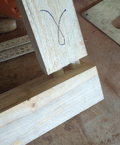
This is the tenon part of the jig. As you can see, it’s simply a horizontal piece onto which is fixed another bit of 100x50x3mm aluminium section. The additional shaped bit which is affixed to that holds the component vertical so the tenon can be machined into the end of it.
Like so! Note that the centre of the potential joint has been marked on the top of what will become the tenon.
Also note that the ‘faceplate’ of ply has access apertures cut into it so that the adjustable clamps can be moved from side to side to accommodate the vertical stock for the tenon.
The Jig template is clamped to the frame with the aperture centred over the centred of the potential joint. The template copying guide on the router is inserted into the aperture, and the router is guided around the outside of the aperture, carefully of course! What’s left after it’s done cutting is what will be the completed tenon.
Which looks a bit like this.
Highly precise and seriously accurate mortise and tenon joint.
Like I was saying about ‘craftsman in a box’!
And if you want to get a bit serious, double up on your joint.
More detail on how that is achieved to come as well!


Sometimes it’s easier and quicker to create a mortise each side of the joint and join them with a ‘floating’ tenon, like this. The process is exactly the same as creating the mortise shown above, but in the end of the component in which you would have otherwise created a normal tenon.
The beauty of this approach is that you can create lengths of tenon ‘stock’ and simply cut them to length – each double the length of the depth of the mortises.
The size of the ‘stock’ (or the ‘floating tenon’) is determined by the length, breadth and diameter of the router bit used to create the mortise. More of that in detail later.
The front of the tenon part of the jig can be created such that the face holding the component to be machined can be angled front to back. If, in the process, you angle the component from right to left at the same time you can create tenons at virtually any angle up to 45 degrees in the X,Y and Z axis. Lots of fun if you are creating chairs, for example.
Or a bit of creative exotica like this at left:
What about if you just want to work with ‘same old, same old’ right angles, like in cabinetry?
As Arnie famously said: ‘No problemo’,
And drawers made using exposed, wedged tenons give an interesting visual take to a two- drawer cabinet. This image is of the drawer being dry fitted but you get the idea in the image above it.
Remember I mentioned that the Flynnymijig can be optioned such that the mortises/tenons can be machined in almost infinite angle variations across the X, Y and Z axes? The images below show what can be achieved when you are no longer constrained by ‘rectilinear’ (right angle) design constraints.
This prototype shows the transition between rectangular components being shaped and sculpted into organic shapes. It takes the piece from craftsmanship to sculpture, art.
This piece is the culmination of that segue from rectilinear to organic. The timber is Redgum, and all that is required for our masterpiece is the sheet of laminated safety glass on the top.
From craft to sculpture. People pay big money for good craftsmanship. They pay lots more for art!
When the creative ‘drives and juices’ get really pumped up and you start expressing curves in three dimensions, that’s when life gets seriously interesting!
What this prototype is trying to capture is that awkward ‘left to right’ swing of a goanna as it is walking along a bush track.
Now from a different perspective, showing a couple of the joints exploded to show those big loose tenons which hold the whole creation together.
Now all we have to do is to machine off the top of those legs (which are emerging from the piece at all sorts of odd, complex angles, to enable us to sit a glass top on top of our creative masterpiece!
But maybe that’s not quite as easy as it sounds?
Versatility and flexibility is the key. That and the use of the highly creative, innovative computer which you have sitting up there between your ears. But, as the man said, there’s more!
One of the tribulations that mankind has suffered since he first started making furniture is his masterpiece not sitting flat. I daresay you have suffered this yourself. No matter how careful you have been in ‘measuring twice and cutting once’. No matter how precise your gluing up using jigs, squares and so on has been, or how flat your gluing up table is, the mongrel thing still has the ‘death wobbles’ when you try to sit it flat on the floor. You know - it’s only out by a couple of mills, but that’s enough to doom both the project and your sanity.
The Flynnymijig Planar-tarium is here just in time to stop you from throwing yourself under the 3:47 bus to town in despair!
I created this baby when I was learning about using two and three D CAD. We studied planar geometry, and a thing called a ‘Boolean’ function. It was like a death ray – anything in your computer design above a plane was gone at the touch of a button! What was left was exactly planar - horizontal to the floor, for example. I decided to create my own version in the workshop using components I sourced from Bunnings, Mitre 10 and so on. I don’t now if you’ve noticed, but death rays are prohibitively expensive!
Of course, I call it the Flynnymijig Planar-tarium!
It's not particularly pretty, but it works a treat, is quick and easy to make and doesn’t cost an arm and a leg. What I do is to create the piece, then secure it in the ‘boolean jig’ to keep everything in.
What we have here is a seriously basic bit of kit! Start with a coupe of hardwood pallets, then put rails along the sides to keep everything straight and in line. Four uprights, some of those shelving uprights and moveable brackets you get from Bunnings, make sure the rails are parallel with the base, and, voila, instant Planar-tarium!
Put a jig on top of the side rails to support your router, as shown here (details later) and you are ready to go! This image shows ‘Julie’s Table’ inverted underneath, ready to have the ends of the legs machined horizontal to the plane of the base, I will then invert the piece, do the same thing with the top arms and voila: masterpiece (or something like that!)
Wherever the flat bottom of the router bit cuts horizontally results in the plane you are looking for. Sounds complicated - it’s not.
But it does work a treat.
This process works as easily on the legs of that that basic rectilinear coffee table that you are creating, to setting up planes on this little sculptural creation (below) where there isn’t a straight line in sight. Bottom line: without the Flynnymijig Planar-tarium on the job, it’s just about impossible!
Think of the possibilities you might be able to create having access to one of these babies!
And it’s exactly the same process for a full-sized dining table with legs emerging at all sorts of impossible angles as it is for a modest hall table. Larger piece, larger Planar-tarium!
Speaking of possibilities. Let’s talk about rails holding the top of a table together. Now everyone knows that you need four rails, one at the top of each leg, to hold the frame rigid in anticipation of fitting the top, right? But what if you don’t? What if you think outside the square, particularly if your creation has vertical pieces (legs) that aren’t necessarily at right angles to where the rails should be and emerge from your masterpiece at all sorts of exotic angles?
Why don’t we make up a frame, machine some tenons into the tops of each of the legs (planar to the base), then machine mortises into the frame?
Stick it all together like Lego and: voila!
‘You can’t do that!’ I hear you say.
‘You most certainly can’, is my response, and here’s the proof!
I’ve done exactly that with this little creation. You can see that both the planes for the top and the bottom of the legs are ‘co-planar’ – they are horizontal to each other. A solid timber hardwood top will be attached to the frame using ‘table clips’ to accommodate movement in the top.
This how it was done. The tenons were machined into the tops of the legs using the Flynnymijig template in conjunction with the Planar-tarium.
I simply located the tenons over the underside of the frame, marked the outsides of the tenons with a marking pen directly onto the longitudinal members of the frame, located the relevant mortise jig aperture over the mark, and voila: like a bought one! You won’t get much more precise than this!
Sounds complicated, but very easy after a demonstration
The above essay provides only an overview of the methodology behind my Flynnymijig and the Planar-tarium. The use of both, combined with some pretty basic design parameters (which I plan to cover during various Facebook posts), and you, too, can be ‘Flynnymijigging for Fun and Profit!,
And for me? At my age and after pretty much a lifetime of development and fine tuning, I can’t wait to see what some of you guys can achieve when the penny drops that all that stands between you and innovative furniture genius is a bit of creative courage and the capacity to ask the very simple question:
‘What happens if I just do this . . . . .


